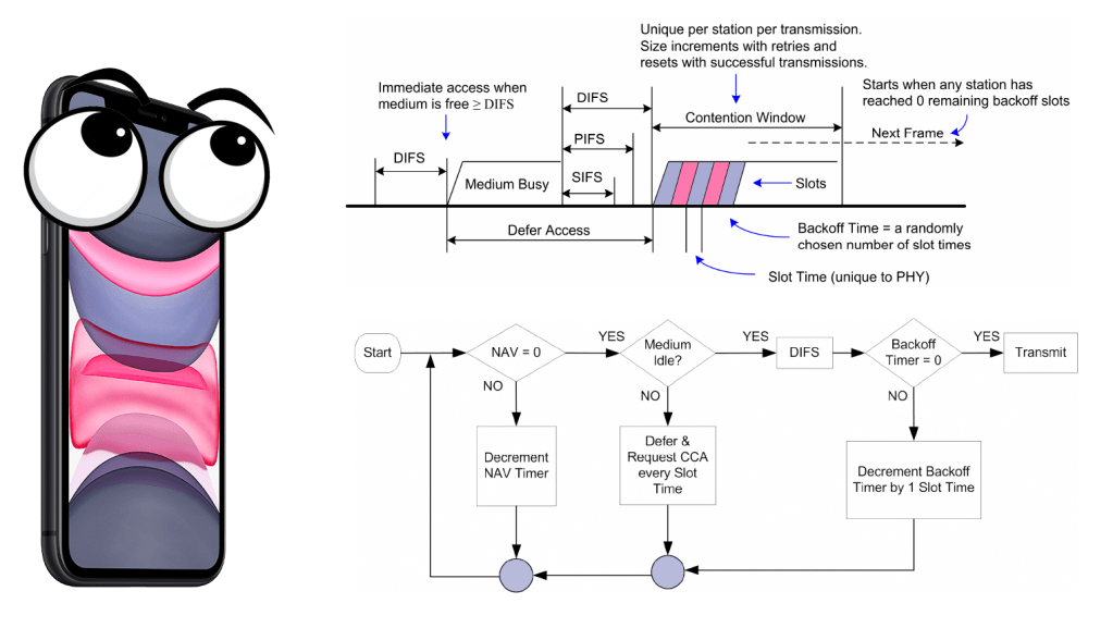
Graphic above is a good explanation on what a client is doing before it is allowed to send, because you already now that wireless is a shared medium so we cannot all send at once because that will create a collision. For example, if you attend a concert you will not be able to understand every word people are saying (maybe, because they are all screaming).
First we we need to understand the different durations of a slot time, DIFS and SIFS. We also have for AIFS, EIFS and a few more. I will not go deeply into details about each interframe spacing, but rather just try to explain the graphic above. I recommend to read the PW0-270, PWO-205 or just read the standard.
- DIFS = SIFS + (2 * Slot time)
- EIFS = aSIFSTime + (8 x ACKSize) + aPreambleLength + aPLCPHeaderLngth + aSIFSTime + (2 x aSlotTime)
| Standard | Slot time (µs) | DIFS (µs) | SIFS (µs) |
| IEEE 802.11-1997 (FHSS) | 50 | 128 | 28 |
| IEEE 802.11-1997 (DSSS) | 20 | 50 | 10 |
| IEEE 802.11b | 20 | 50 | 10 |
| IEEE 802.11a | 9 | 34 | 16 |
| IEEE 802.11g | 9 or 20 | 28 or 50 | 10 |
| IEEE 802.11n (2.4 GHz) | 9 or 20 | 28 or 50 | 10 |
| IEEE 802.11n (5 GHz) | 9 | 34 | 16 |
| IEEE 802.11ac (5 GHz) | 9 | 34 | 16 |
In 802.11 we use CSMA/CA rather than CSMA/CD, so we need a way to avoid the collisions since we cannot detect them. One way to do this is the carrier-sense mechanism. We have two types, physical and virtual-carrier sense that can determine the state of the medium.
Both of these should report the medium as idle before the client can continue the DCF process. The physical carrier-sense mechanism shall be provided by the PHY, and listens to the RF medium for non-802.11 or a preamble. It is not always possible to get read the NAV timer (we get to that) to get the duration value, so the physical-carrier sense is used to listen for RF.
- to determine whether a frame transmission is inbound for a station to receive. If the medium is busy, the radio will attempt to synchronize with the transmission.
- to determine whether the medium is busy before transmitting.
This is known as the clear channel assessment (CCA)- You can read more about CCA at a blog post by David Coleman here)
The two different ways is Energy Detect (ED) and Signal Detect (SD) where as the client would «wait» if it could detect a preamble 4db SNR above the noice floor, or with energy detect 20db above the signal detect threshold.

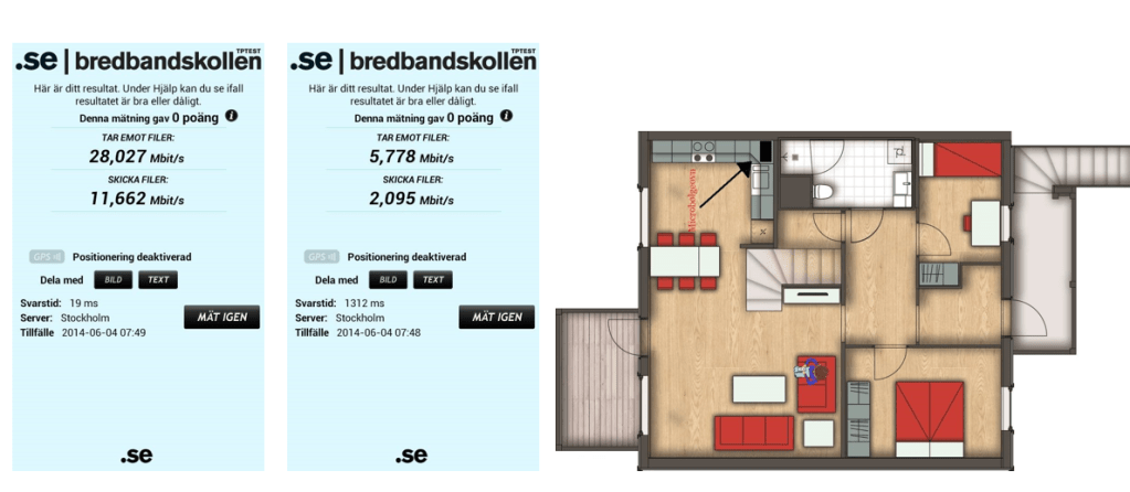
This very basic drawing explains it a bit, but remember that the your phone or PC is NOT a spectrum device, and will most likely give some false positives with the energy detect.
Nevertheless, take a look at the picture below, that shows that this works OK, since me turning on the microwave in 2014 I got from 19ms response time to 1312ms response time. This was not good news for the Playstation with only 2.4Ghz, and not for 5 neighbors. (since my Microwave was next to his livingroom)
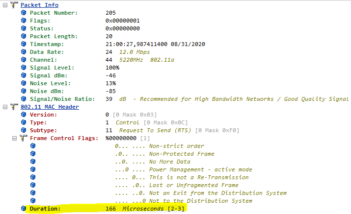
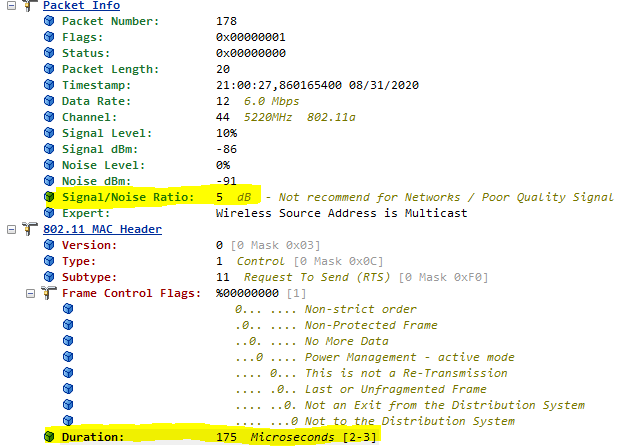
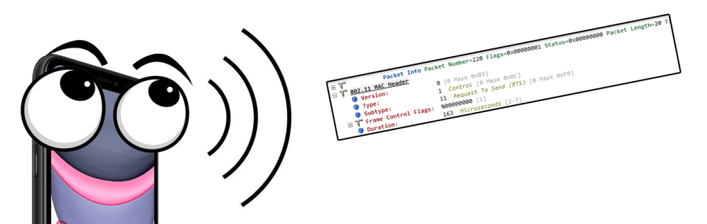
Next up is virtual carrier-sense, and this is provided by the MAC. This is also what we call the network allocation vector (NAV). The NAV maintans a prediction of future traffic based on the information that is announced in a RTS/CTS (IEEE-802.11-1999) frame for example. Below you can see a RTS frame, with a duration value of 166 Microseconds, and the next picture you see a RTS frame with only 5dB SNR that was captured correctly.
When a client see these duration values it know how long the medium will be busy, and then sets its own value (NAV) and start counting down until it reaches zero.
You need to remember that both virtual carrier-sense and physical carrier sense is all happening at the same time.
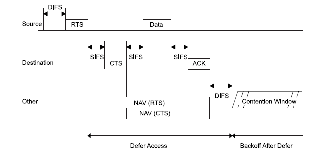
As you can see from the graphic above you can see how a client would reset their NAV timer of what it could see in the Duration field of the RTS/CTS frame. If it did not hear either RTS or CTS, that would be fine. Several other frames could also reset the NAV timer, but here I am just focusing on RTS/CTS.
So how long have we come now, let us take a look at this picture again.
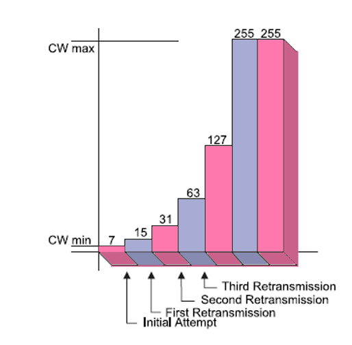
The NAV timer has reached zero, but that is not all. It is very easy to understand that clients would need more than just wait the duration value of another frame before transmitting, or else everyone would send at the same time. That is why we also have the Backoff timer. – a number that goes by the name «Contention Window»
The backoff timer is randomly chosen and works as a countdown. The speed of this countdown is the time of the SlotTime of the PHY.
Backoff Time = Random() x aSlotTime
- 15 and 1023 for 802.11a/g/n/ac
- Typically 15
- 31 and 1023 for 802.11b
- Typically 31
| Standard | Slot time (µs) |
| IEEE 802.11-1997 (FHSS) | 50 |
| IEEE 802.11-1997 (DSSS) | 20 |
| IEEE 802.11b | 20 |
| IEEE 802.11a | 9 |
| IEEE 802.11g | 9 or 20 |
| IEEE 802.11n (2.4 GHz) | 9 or 20 |
| IEEE 802.11n (5 GHz) | 9 |
| IEEE 802.11ac (5 GHz) | 9 |
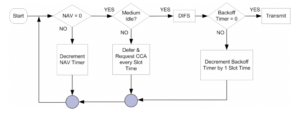
When the client need to send a frame it waits a DIFS and then start the random backoff-timer countdown, at every SlotTime.
That is every 9 us for 802.11ac for example. For each countdown the client is doing a CCA to see if someone else is sending, and if that is true it would wait for the transmission to be done, then wait a DIFS and resume the countdown.
In the end, it will finally reach zero and if the NAV and backoff-timer both are zero there goes the frame.
Of course if the client did not get an ACK back for a frame, it would need to try again, but that would make the contention-windows increase exponentially.
It would seem like it takes forever to send a frame, and I hope I explained it somewhat interesting. If you like to learn more, here are the resources I used to write this. All pictures are borrowed from the standard or the PWO-205 book, I just added some fancy colors.
- Certified Wireless Analysis Professional – Exam PW0-205
- Certified Wireless Analysis Professional – Exam PW0-270
- Part 11: Wireless LAN Medium Access Control (MAC) and Physical Layer (PHY) Specifications (I read from an oldy, the 802.11 – 1999 edition)
